
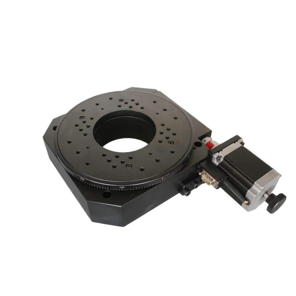
Vertical vs. Horizontal Mounting of Servo Hollow Rotary Actuators: Sizing for Tilting Moments, Gravity Torque, and Lubrication Life
Compare vertical vs. horizontal mounting of servo rotary actuators. Check tilting moments, gravity torque, lubrication and brakes before requesting an RFQ.
For vertical vs. horizontal mounting of servo hollow rotary actuators, check two separate effects: the bearing's tilting moment from axial overhang, and the motor's gravity torque from radial eccentricity. They use different center-of-gravity distances. Balancing a fixture can reduce gravity torque without removing its cantilever bearing moment.
This guide helps automation machine builders, mechanical engineers and OEM buyers compare servo hollow rotary actuators and precision rotary tables before an RFQ. Use the checklist below to prepare your load data, then request an application review.
Published and technically reviewed: November 3, 2026. Scope: global engineering screening for electrically driven rotary positioning assemblies. Here, horizontal means a tabletop face with a vertical rotation axis; vertical means an upright face with a horizontal rotation axis. Inverted and inclined installations need separate approval. Examples are hypothetical calculations, not measured product tests, certified safety designs or service-life guarantees.
Key Conclusions for Procurement & Engineering Teams
- An axial rating alone cannot approve vertical mounting. Check radial force, overturning moment, bearing retention, housing stiffness and mounting bolts against the selected model's limits.
- Keep two CG offsets separate. Axial overhang determines the gravity-induced bearing moment; radial eccentricity determines gravity torque about a horizontal rotation axis.
- Include dwell and lowering in motor sizing. Check continuous and peak motor torque, gearbox ratio, thermal conditions and regenerative energy across the complete cycle.
- Request an orientation-specific lubrication instruction. A universal grease fill percentage, grease chemistry or seal material cannot be specified from mounting angle alone.
- Separate holding from stopping. Obtain the brake's actual dynamic-stop limits and assess what happens on loss of electrical power or clamp pressure.
Visualizing Horizontal vs. Vertical Mounting
The diagram isolates gravity loads on a centered tabletop fixture and an overhung upright fixture. External process forces, acceleration and fastener reactions must be added in the actual design.
Force Transformation: Axial Load, Radial Load and Tilting Moment
For a stationary assembly with total rotating mass m and gravity g = 9.81 m/s², a centered tabletop load gives Fa = m × g. An upright face gives Fr = m × g and, with axial overhang L_cg, a bearing tilting moment:
M_tilt = m × g × L_cgL_cg is the distance along the rotation axis from the bearing load center to the combined fixture/workpiece CG. A tabletop fixture can also create a moment if its CG is radially off-axis. Include tooling, workpieces, hoses and all process forces in each load case; multiple stations do not automatically balance one another.
Reproducible screening example
Assume a hypothetical 12 kg rotating fixture, an axial overhang of 120 mm and a bearing roller pitch diameter of 100 mm. These are example inputs, not a ServoRotary model specification:
Fr = 12 × 9.81 = 117.72 N
M_tilt = 117.72 × 0.12 = 14.1264 N·m = 14,126.4 N·mm
2M_tilt / dp = 2 × 14,126.4 / 100 = 282.528 N
An axial capacity figure cannot answer whether this combined radial-and-moment load is acceptable. Reducing overhang from 120 mm to 60 mm halves the gravity-induced tilting moment while leaving the payload weight unchanged.
Crossed-Roller Bearing Load and Fatigue Life
The THK cross-roller ring selection method, pp. B18-12–B18-13 uses:
Pc = X × (Fr + 2M/dp) + Y × FaHere Pc, Fr and Fa are in N; M is in N·mm and dp in mm. Use the actual bearing pitch diameter, not the actuator frame size. In this method, X = 1, Y = 0.45 when Fa / (Fr + 2M/dp) ≤ 1.5; above that threshold use X = 0.67, Y = 0.67. For pure axial load (Fr = M = 0), THK specifies X = Y = 0.67.
For the example upright fixture with no external axial force, Pc = 117.72 + 282.528 = 400.248 N. The centered tabletop gravity-only case gives Pc = 0.67 × 117.72 = 78.8724 N. The approximately 5.07 ratio belongs to these assumptions; it is not a universal vertical derating factor. With 60 mm overhang, the upright equivalent load falls to 258.984 N.
For this catalog's basic nominal-life convention:
L10 = 1,000,000 × (C/Pc)^(10/3) revolutions
Lh = L10 / (60 × n) hours, for constant-speed rotation at n rpm
C is the bearing's catalog dynamic rating. L10 is a statistical fatigue estimate at 90% survival under the stated conditions, not a minimum operating life or grease-life prediction. Preload, shock, temperature, changing loads, oscillation, lubrication and mounting require the manufacturer's corrections. Check static capacity, stiffness and the complete actuator separately; no failure-hour prediction follows from this example.
Gravity Torque Reversal and Backlash
When the rotation axis is horizontal, radial CG eccentricity R_cg creates gravity torque. Define θ = 0° at 3 o'clock and positive rotation counterclockwise. The gravity-compensation torque at the output is:
T_comp(θ) = m × g × R_cg × cos(θ)The torque exerted by gravity has the opposite sign. Its magnitude is greatest at 3 and 9 o'clock and zero at 12 and 6 o'clock. For an inclined axis, use the gravity component perpendicular to that axis.
For the same 12 kg assembly with 50 mm radial eccentricity, peak compensation torque is 12 × 9.81 × 0.05 = 5.886 N·m. This eccentricity is independent of the 120 mm axial overhang used for bearing sizing.
As total transmitted torque reverses, contact can move between opposing gear flanks and disturb position. The reversal angle depends on acceleration, friction and process forces as well as gravity; knock is not inevitable at every top or bottom crossing.
- Balance the assembly: reduce radial eccentricity, then recalculate the added counterweight's bearing load and inertia.
- Specify lost motion under load: obtain a measured acceptance limit for the required direction reversals, rather than assuming all preloaded gears have one backlash value.
- Consider a direct drive rotary stage: removing gearing removes gear backlash, while bearing compliance and control errors still require checks.
- Tune feedforward after mechanical review: compensation may improve tracking but cannot remove physical gear clearance or replace load retention.
Lubrication Migration and Seal Life
Orientation can affect grease retention, base-oil migration, replenishment access and leakage paths. It does not establish that the upper raceway will run dry after a fixed number of hours. Low-speed oscillation can also limit lubricant film formation; centrifugal redistribution should not be assumed for an indexing table.
NSK's grease lubrication guidance makes fill quantity dependent on speed, housing space, grease and operating conditions. Its general bearing guidance is not an actuator-specific filling instruction. Do not impose a universal 70%–80% cavity fill or substitute grease based only on NLGI grade.
Ask the actuator supplier to document:
- Approved mounting orientations and the exact lubricant designation, compatibility and factory fill quantity.
- Whether the assembly is sealed for life or relubricatable, including access, quantity and service interval for the actual duty.
- Seal material and geometry compatible with lubricant, temperature, environment and leakage requirements; FKM is not automatically required for vertical use.
- An installed-orientation acceptance check for leakage, temperature and running torque. Do not mix greases or refill a sealed assembly without approval.
Product Reference: Rotary Platforms and Tilting Assemblies
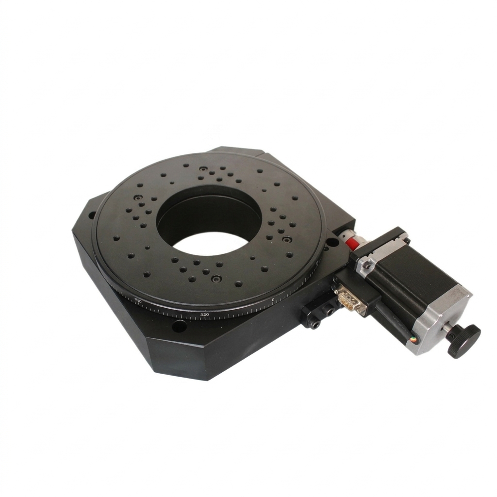
A tilting rotary table can change the rotary axis angle during the process. Evaluate load cases throughout both axes' travel, including the largest CG offset and power-off position.
Motor Sizing and Holding Brake Duty
Output demand includes inertia, friction, process torque and signed gravity compensation. At a dwell, use gravity torque at the actual stopping angle rather than assuming its peak at every angle.
For initial motoring screening of a geared assembly:
T_motor ≈ T_output / (i × eta)
i = motor speed / output speed; eta = motoring transmission efficiency
I_hold ≈ T_motor,hold / Kt
T_RMS = sqrt(sum(T_motor,k² × t_k) / sum(t_k))
Use the motor's specified current/torque convention for Kt. For illustration, i = 10 and eta = 0.90 convert the 5.886 N·m output gravity peak to approximately 0.654 N·m at the motor, before friction and other loads. Direct drive has i = 1; backdriving efficiency and holding behavior need separate supplier data.
Include dwell in RMS torque, check continuous low-speed capability and the torque-speed envelope, and verify peak duration, mounting heat dissipation and ambient temperature. Lowering may return energy to the drive: size its regeneration path for kinetic energy, gravitational potential-energy release and repetition rate. No fixed motor temperature or universal torque margin follows from orientation alone.
Holding, stopping and power loss
Beckhoff's AM8100 holding-brake instructions distinguish holding from service braking and specify conditional emergency-stop limits for that motor family. Limits are model-specific; neither a universal ban nor a fixed number of stops applies to every servo brake.
Request the selected brake's holding torque, allowable stop energy, inertia and speed limits, wear allowance and engagement delay. A stationary output clamp may resist process torque, but its dynamic-stop rating and behavior on pressure loss must be verified. An ordinary pneumatic clamp must not be assumed to retain a gravity-driven load after loss of air.
Document controlled stopping, power-loss retention and brake sequencing with the machine's responsible safety engineer. A brake or clamp option alone does not establish a safety function.
For a preliminary discussion, send the motion profile and worst-case dwell angle with your payload and CG data.
Comparison: Horizontal, Vertical, Inverted and Trunnion Mounting
This matrix is a screening guide. Entries describe gravity loads; process and dynamic loads must be added. Scroll horizontally to compare all columns on small screens.
| Selection item | Horizontal tabletop | Vertical upright face | Inverted | Inclined / trunnion | RFQ action |
|---|---|---|---|---|---|
| Bearing gravity load | Axial; moment if off-center | Radial plus moment from axial overhang | Axial in the opposite direction | Combined axial and radial components | Supply CG coordinates for every load case |
| Capacity and life | Verify combined loads | Use actual radial and moment limits | Verify retention and bolt load path | Evaluate across the tilt range | Request model-specific static, fatigue and stiffness checks; no blanket multiplier |
| Motor gravity torque | Zero about an ideal vertical axis | Angle-dependent if radially eccentric | Zero about an ideal vertical axis | Depends on tilt and eccentricity | Check signed peak and RMS motor torque including dwell |
| Backlash exposure | Reversal can occur during acceleration or processing | Gravity can add torque reversals | Process and inertia can reverse torque | Reversal depends on the full motion profile | Define loaded lost-motion and settling acceptance limits |
| Lubrication | Follow assembly instructions | Confirm orientation approval and lubricant access | Check leakage and service access | Check changing orientation and oscillation | Obtain lubricant, quantity and maintenance instructions |
| Seals and contamination | Match operating environment | Check lowest leakage path | Check dripping onto workpieces | Check throughout motion | Specify acceptable leakage and material compatibility |
| Holding and stopping | Assess external process torque | Retain gravity-driven loads when required | Secure tooling and suspended assembly | Evaluate worst-case power-off angle | Verify brake/clamp ratings and loss-of-power or pressure behavior |
| Cost comparison | Obtain an application-matched quote | Include any bearing, motor and brake changes | Include retention and access provisions | Include both axes and support structure | Compare installed cost, maintenance and acceptance scope; no assumed price premium |
Engineering & Procurement Checklist for Vertical Duty
Before releasing a purchase order, record these items with the supplier:
- Geometry: total rotating mass, CAD CG coordinates, axial overhang from bearing load center, radial eccentricity and mounting-angle range.
- Bearing and structure: combined-load calculation for the actual bearing, static margin, fatigue assumptions, allowable deflection, bolt pattern and base stiffness.
- Motion profile: inertia, speed, acceleration, lowering, process forces, dwell angles and repetition rate; include counterweights and cables.
- Motor and drive: ratio, efficiency assumptions, peak/continuous torque, RMS duty, thermal limits and regeneration capacity.
- Positioning: loaded lost motion, bidirectional repeatability and settle-time acceptance under the actual installation orientation.
- Lubrication and sealing: written orientation approval, approved lubricant and quantity, replenishment method and leakage limits.
- Stopping and retention: brake/clamp holding and dynamic ratings, sequencing, power/air-loss behavior and the machine safety review.
- Commercial acceptance: exact model/options, drawing revision, installed-duty test conditions, warranty exclusions and responsibility for final sizing sign-off.
Total Cost of Ownership: Compare the Same Duty
Compare quoted configurations against one load and acceptance specification. A larger frame is not automatically needed if shorter overhang or a supported fixture resolves the moment constraint; a counterweight can reduce gravity torque while increasing inertia and bearing load.
Use your own production figures to estimate:
Installed lifecycle cost = purchase + integration + planned maintenance
                         + expected downtime + replacement/requalification
Expected downtime cost = assumed interruption hours × site-specific cost per hour
Label downtime assumptions and obtain installation-specific service estimates. A generic dollar loss, motor lifetime or grease replacement interval cannot be inferred from mounting orientation.
Frequently Asked Questions
Why do catalog axial load ratings not determine vertical mounting capacity?
Vertical mounting puts gravity perpendicular to the rotation axis, creating radial load and an overturning moment when the payload overhangs the bearing. Check the selected actuator's combined-load limits, mounting approval and duty cycle; an axial rating alone cannot approve the installation.
How does gravity torque affect backlash in a vertical rotary table?
An eccentric payload on a horizontal rotation axis produces angle-dependent gravity torque. If total drive torque reverses, gear contact may transfer between tooth flanks and disturb positioning. Acceleration, friction and process forces affect when this happens; balance, preload and control tuning require application validation.
Can a servo motor holding brake perform vertical emergency stops?
Only within its manufacturer's explicit dynamic-stop limits, if provided. A holding brake is generally intended to retain a stopped load, not to perform repeated service braking. Confirm inertia, speed, permitted stop energy, brake timing and power-loss behavior; a motor brake alone does not establish personnel protection.
What lubrication changes are needed for vertical mounting?
Obtain the actuator manufacturer's written approval for orientation, grease type, fill quantity, replenishment access, service interval and seals. There is no universal vertical grease percentage or mandatory thickener or seal material. Do not add grease or mix lubricants without checking the selected assembly's instructions.
How is equivalent bearing load calculated under an overturning moment?
For the cited THK cross-roller ring method, Pc = X × (Fr + 2M/dp) + Y × Fa. Use the catalog's load-dependent X and Y values, consistent moment and diameter units, and the actual bearing pitch diameter. Other bearing designs and complete actuators may require different calculations; nominal fatigue life is not a warranty.
Prepare a Vertical-Mount RFQ with ServoRotary
Send the assembly drawing, payload/CG data, required orientation, motion cycle, positioning tolerance and environment to ServoRotary's technical sales team. Request a model-specific response covering load limits, motor/brake options, lubrication instructions and acceptance conditions before placing an order.
Explore hollow rotary actuators and tilting rotary tables to shortlist configurations. Confirm available options and written sizing responsibility in the quotation; this guide does not certify a particular installation.
Sources & References
Sources checked November 3, 2026. Manufacturer guidance applies to the product families identified below and does not establish ServoRotary product ratings.
- THK — Cross-Roller Ring, Nominal Life and Selection Criteria, pp. B18-12–B18-13. Basis for the catalog-specific equivalent-load equation and nominal fatigue-life method. Read the technical PDF.
- NSK — Chapter 10.2: Grease Lubrication. General guidance on grease composition, fill quantity and replenishment; not a filling specification for a sealed actuator. Read the lubrication guidance.
- Beckhoff — AM8100 Holding Brake. Product-family guidance distinguishing holding, service braking, conditional emergency stops and additional measures for vertical axes. Read the brake instructions.
Author

Categories
More Posts
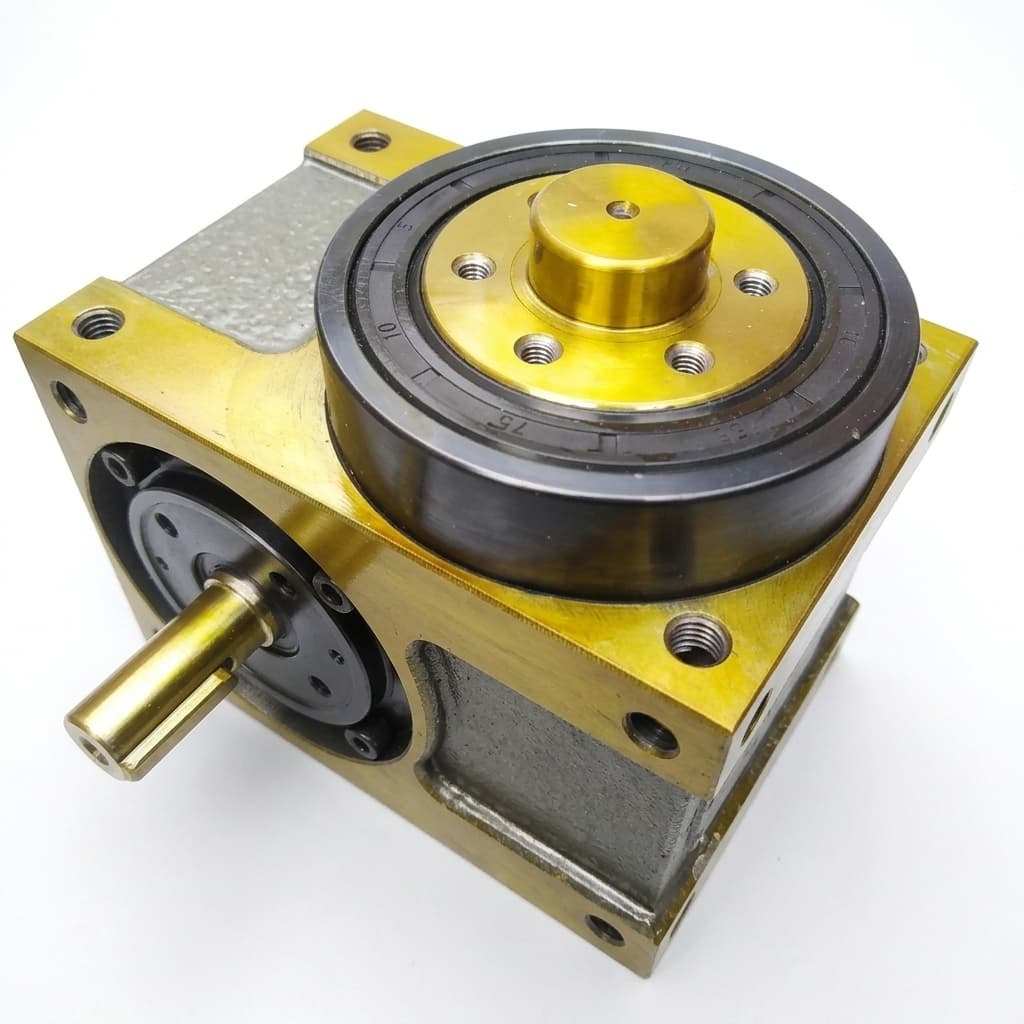
Direct Drive vs Servo Hollow Rotary Tables: A Procurement and TCO Comparison
Direct Drive Rotary vs Servo Hollow Rotary Tables for precision indexing: compare backlash, inertia, tuning effort, lead-time risk, and TCO before RFQ.
2026-W20 Rotary Sourcing Update: Tariff Risks
Week-20 buyer brief on servo hollow rotary tables: U.S./EU trade-rule shifts, bore/load exposure points, and RFQ controls buyer teams must lock this week.
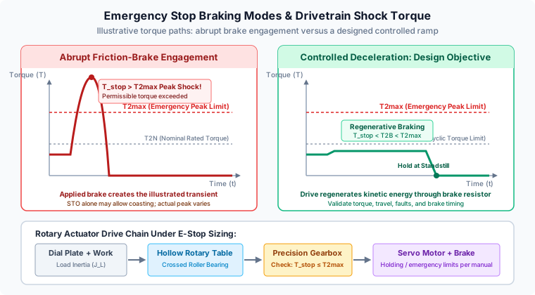
Emergency Stop Deceleration Shock and Holding Brake Sizing in Servo Rotary Actuators: Peak Impact (T2max), Dynamic Braking, and Safe Stop Compliance
Size emergency stop torque and holding brakes for servo rotary actuators. Compare T2max, SS1/STO and braking resistor power; use the engineering RFQ checklist.